This blog is to document the design and construction of my Kawasaki Voyager XII powered reverse trike (two front wheels, one rear wheel).
Sunday, April 28, 2013
Body Lift
So yesterday I removed connections (shifter, front body brace, steering column, etc.) and unbolted the body. I installed 1.25" shims to raise it. I also shimmed the front end to increase the caster angle - it was only about 1.9 and it should be at least 5 degrees; I put in a 1/4" shim and is at least 4.3 degrees now. I think it to be a little more since I also dialed the suspension tighter which will increase the angle. I had to then modify the front brace and enlarge the hole for the steering column to get things to fit.
On a whim I pulled the front shocks and found out the left one was froze hard. I should have new ones by noon today. After I put those on I plan on taking her for another spin.
I finally got the front brakes bled last weekend - lots of pumping with my vacuum bleeder. I put some tires on that I got from the junk yard (about 70% tread) and tried her out. Here's the video:
This little ride was a lot of fun, but the tires rubbed the body in even the slightest of turns (with no bumps). The back end got loose when I laid into the throttle, but I didn't have the rear cowling on yet (about 40lbs). The tires are a little big, and I have to put some spacers in to raise the body a little - and probably shim forward the front axle. The body is currently as far rearward as it can go (shell is against the rear frame), but the front tires are about 1.25 inches off center of the fender wells towards the rear. I need to figure this out yet. Hopefully I will not have to disconnect the hydraulics and re-bleed them (pain).
Been too busy to post lately, but here's an update:
I fixed the throttle cable (it was pinched), got the battery tray fabricated and mounted, bolted down the front lateral bracket and fab'd the support brace, connected the shifting linkage and clutch line (pain), extended the choke cable, and probably a lot more little odds and ends since the last post. Luckily its been warm so I could more comfortably run it a bit with the garage doors open.
Oh ya, something in the headlight circuit did't like the way I put the switch in (on the bike they were on all the time if the engine was running). As long as they were switched on when you started it, they stayed on, but if you turned them off, they wouldn't come back on. In any event, after pulling most of my hair out (wasn't really that much to begin with), I re-wired the circuit and they work right now.
Below is a video and a few pics. Now I'm going to go install the steering column and attache and bleed the hydraulic lines - not looking forward to that.
I just added this since I didn't have a vid on here with it running good yet.
Here's where I decided to mount the battery. This allows me to use a car battery and where the original battery was is pretty tight and buried in wiring and relays that were attached to the fairing (see the picture later).
Here I have my boat battery connected for now. It's a little big for the tray. (I made it to fit a group 26 battery, also the battery charger is connected as well.)
You can also almost see the automotive battery cables that I installed to extend to the new battery location.
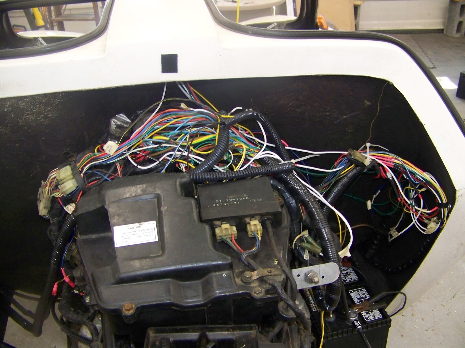
Above, where you see the wire nest, is where the battery was originally located. It's now packed with relays (for the signals, headlight, main, etc. - there's seven of them), the reserve lighting device, turn signal cancel unit, cruise control control unit, and one of my missing daughters that we haven't seen since just after Christmas.
The front end is not very rigid on its own. My kit instructions say to install a support, so I made on. It consists of a cross beam that bolts to the fenders and under the radiator and a support arm that goes between the beam and the frame (its painted white, in place but not bolted down yet):
Here's with the support arm off:
In order to use the original motorcycle choke, I had to extend the cable so I made a junction box cut the cable end and spliced it with half of the original throttle cable.
Shifter and Clutch Connections
Alright, now this was about impossible to reconnect with the body on the frame. Even with the tire off, there is no room to get two hands in to bolt up the linkage or to attache the hydraulic line . . . but an hour later I finally got it (with help from the wifey).
Lastly, below you can kind of see the return spring that I had to add to the throttle cable to make sure the throttle would return when released. I used part of an old bicycle brake cable (the barrel end fit) and bolted the other end to a spring - Works great!