Dash Out of Vehicle
I had to pull the dash out to weld in the passenger side "glove box" which is really a shelf made of expanded metal. That gave me a chance to easily paint it torque and lock-tite the brake bolts, and finish mounting the speedo gearbox and cables. Here's some pictures:

Yes, the speedo cable is held to the gearbox with zip ties. The threads on the cable fitting fit over (without engaging) the gearbox and all the ties do is keep it from falling out. Good enough to keep the square end of the cable engaged with the gearbox. There is a 2 inch piece of square drive between the gearbox and the instrument cluster to drive it on that side. I fabricated it out of the motorcycle speedo cable with a little extra braze to square off the cut end. I got the gear box from Surplus Center for a few bucks; its 2.5 to 1 which is within about 10% of what I needed to get the speedo to read right. I plan on using a GPS for actual speed. I hooked up the speedo so it looks better when driving and to allow the cruise and self-canceling signals to work of the distance sensor (which is just behind the gearbox on the top of the speedo.
Parking Brake
In a earlier post, I promised some better picture of how the parking brake (fab'ed from a bar clamp) worked. Here they are:
This one (above) shows the brake engaged. The clamp, mounted under the frame (with the orange button), prevents the bar from releasing the brake pedal until the orange button is pushed. I made a small bracket to hold the bar up out of the way when not in use. The two upward pointing tangs above and to the left of where the clamp mounts to the dash were added to mount the ignition switch.
Above shows the parking brake in the stowed position.
Another few pictures of the parking brake. In the one above you can see the bracket that holds it up when stowed. Also near the top of the pedal you can see where I mounted the the front brake light and cruise cancel switches. Its black and you can see the shiny mounting bolt on its bottom edge. It was quite challenging to fabricate the bracket to hold this switch just right to get both switches to actuate when you want them to and to get in there to mount it.
All Those Wires!
There are a lot more wires than you might think that needed to be extended and routed from the dash back to motorcycle wiring harness. So far, I think I've added about 400 feet of wire!
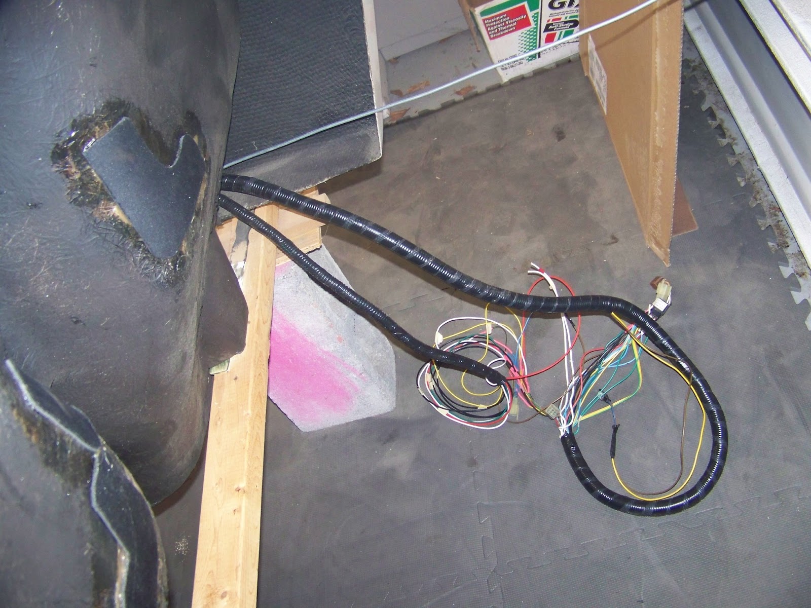
Here's only some of the mess before putting it into conduit:
and on the floor: (the silver cable is the throttle cable)
Below is the extension wires for the right grip controls being prepped for soldering in.
Below shows the extended wires for the radiator cooling fan and the temperature sensor.
Throttle Cable Brackets
The throttle cable will run unsheathed from the front of the frame to the back.
Below is a close up of the rear bracket.
And here is the front bracket. (The hoses you see are for the radiator)
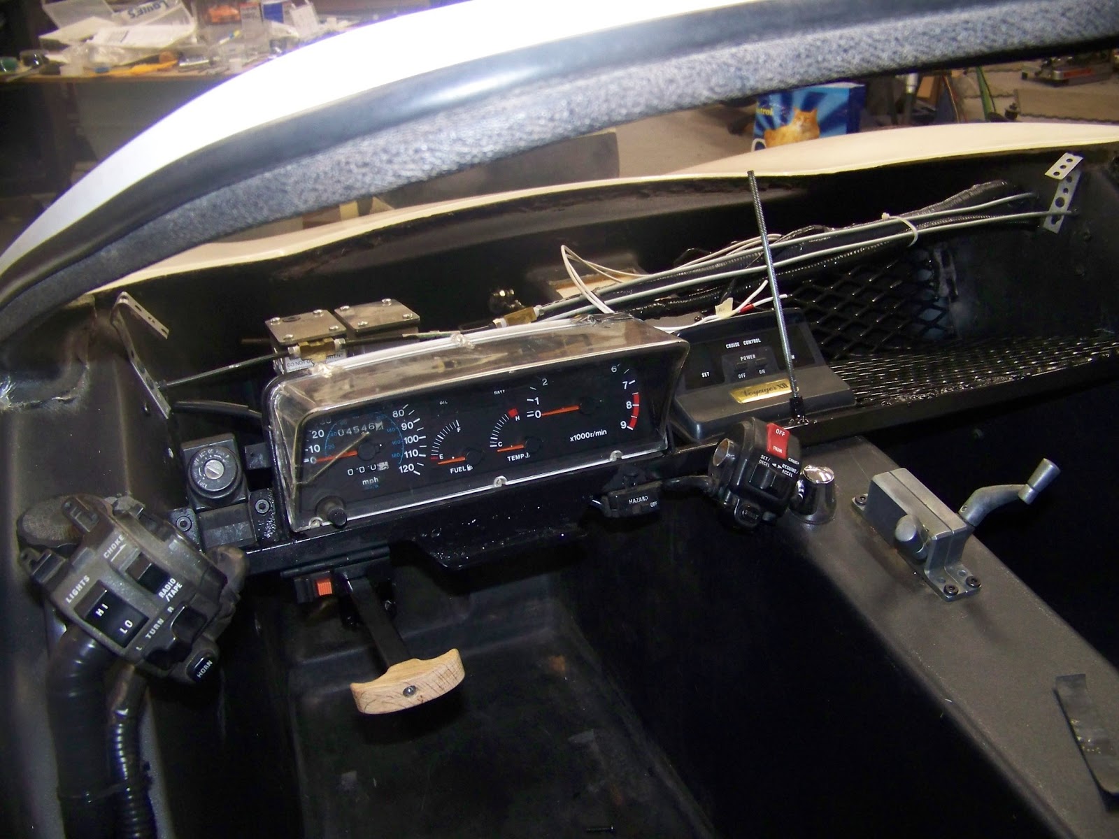
Finished Cockpit Wiring
Here are the wires neatly in the flexible conduit which runs down the passenger side. Just putting all of them in the conduit took nearly an hour.
Above shows the dash installed with all of the control's mounted (except for the steering wheel). Not installed is the shroud for the instrument cluster and the dash cover that sits just above the instruments to hide all the wires, brakes, and such. Below shows the wires exiting the back of the passenger's side of the cockpit, just waiting to be plugged into the motorcycle wiring harness.
This weekend I plan on finishing the throttle cable work, relocating the cruise control unit on the frame, and maybe getting around to suspending the front body (cockpit) slightly above the frame to figure out how to run the radiator hoses and make the final connections.


0 Comments:
Post a Comment
Subscribe to Post Comments [Atom]
<< Home