Clutch and Left-hand Controls, Brake Lines
After pretty much two years off . . .
I spent a good two days cleaning up, picking up, and organizing the workshop. It was a mess from various other projects - I don't think a single horizontal surface had more than two square inches bare. Also, in April of 2011 I bought a sweet little Ninja which has distracted me. You can see it and one of my projects for it here (I also did the custom decal work on the bike): Custom Ninja 250 MufflerSo back to the Reverse Trike Project . . .
The Left Hand Controls:
I finished up the left hand controls this last week or two. This included mounting the remote reservoir for the hydraulic clutch, finishing the clutch lever linkage (to push the clutch master cylinder), modifying the shift lever to better accommodate the left hand controls and extending the wiring harness for the left hand controls (12-16 wires!). Here's some pics:
The master cylinder is under the lever (inside the side channel wall) and the reservoir is on the left mounted in the fender well.
The left controls can be seen here. They are now easy to reach with your thumb and not in the way of pulling the clutch lever. I know the cable look in the way, but they are not - they run down the inside whereas you hand grabs from the outside. The zip ties will be trimmed later.
Here the wiring is exiting the rear of the body. Not shown is the shift linkage and hydraulic line for the clutch that will also be connected to the shifter and will exit here.
Here's the end of the left side wire harness after being extended about 4.5 feet and ran through flexible corrugated wire conduit.
Running the brake lines:
I also recently finished the parking brake actuator and ran the hydraulic lines for the brakes:
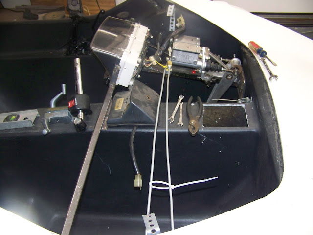
Here you see the lines coming out of the front and rear master cylinders. The fitting towards the right is a automotive style hydraulic brake switch.
A view of the brake lines that will run under the dash - I'll pretty them up a little later, but I know I will have to pull the dash skeleton out to paint it and to mount the motorcycle brake light switch and cruise control cancel switch so that they are actuated by pedal motion.
.
Here are my brake line brackets that I fabricated out of some galvanized steel strap. (The strap was from an Simpson strong tie used for joining construction framing.)

This is the rear brake line exiting the back of the right side channel. Note that the ends of all my lines are taped over to keep out crap.
The Parking Brake:
This is the push rod for the parking brake (the wooden handle comes off and is screwed to the end). The "L" at the end pushes on the pedal. The rod is clamped in place at the dash . . .
by this clamp (the rod goes through the hole to the right of the orange release button). This assembly was made out of an old, $5 bar clamp. The "L" at the end is normally held up in a slot just under the master cylinders. When you want to engage the brake, release it from the holding slot and it will drop down in front of the brake pedal and stop right behind the pedal foot pad. Step on the brake and push the push rod in and it locks in place until the orange button is pushed. The latch assembly (with the orange button) is attached to the dash frame with a hinge to allow it to pivot down when the parking brake is engaged. I'll try to get a better picture of how this works when I remove the dash skeleton for painting later.


